|
|
|
|
|
|
|
|||
| English |
|
Kısım1 Kısım2 Kısım3 Kısım4 Kısım1 Kısım2 Kısım3 Kısım4 Kısım1 Kısım2 Kısım3 Kısım4 |
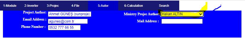
Information about the project can be entered into the system by the project
author. However, updates can be made by the person who approved the project.
The status of the project can be followed from your mobile phone. Username and
password are given at hakan6n@gmail.com.
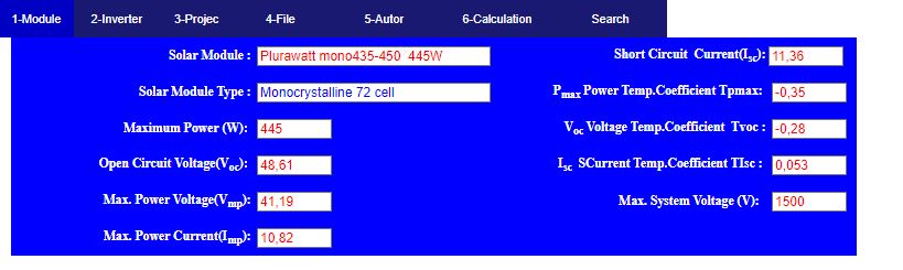
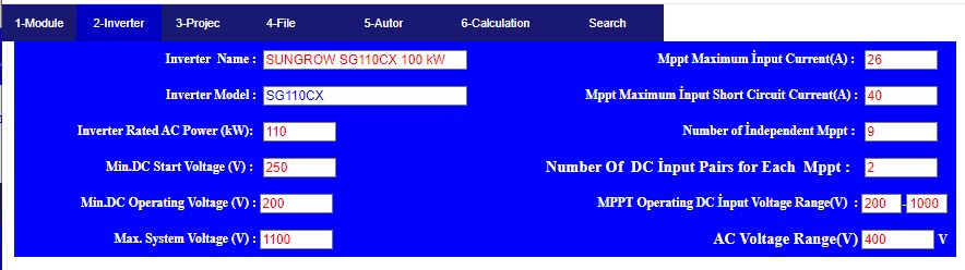
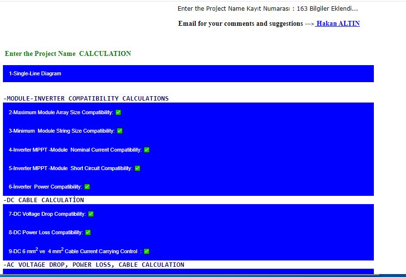
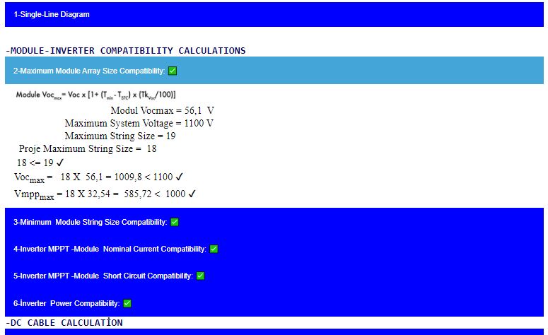
1- Panel-Inverter Compatibility Calculations 2- Voltage Drop Loss Calculations 3-DC-AC Cable Section, Fuse, Switch, Busbar, Current Transformer, Surge Arrester Selection Calculations 4-Single Line Project Drawing 4-File Document Control Technical data of the Solar Panel is entered.
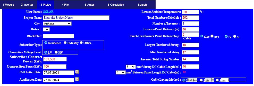
Technical data of the project is entered.
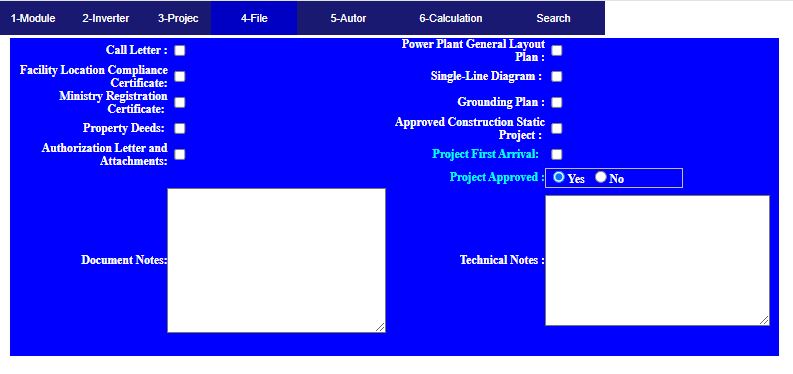
File checking is in progress
The project manager is selected. Only the project manager can update the information
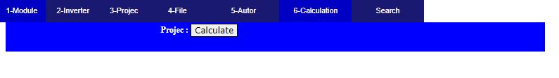
Project control operations are performed by pressing the Calculate button.
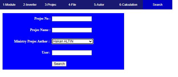
You can search for projects from here.
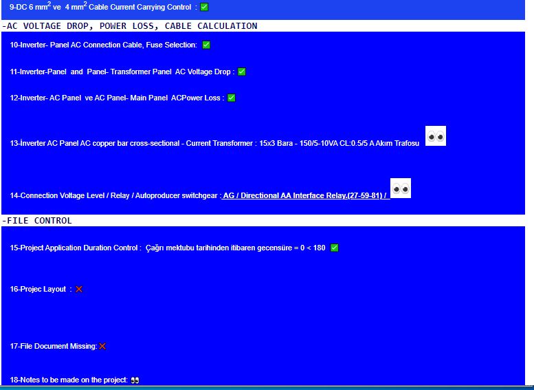
By pressing the Calculate button, the following checks are made and a check mark is placed if appropriate.
A cross mark is placed because the missing files are not completed. Account details are displayed by clicking the buttons.
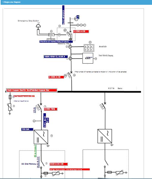
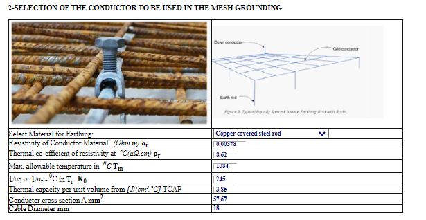
The project draft is drawn on the single line diagram and fuses, switches, surge arresters, current transformers, busbars, sections and relays are selected.
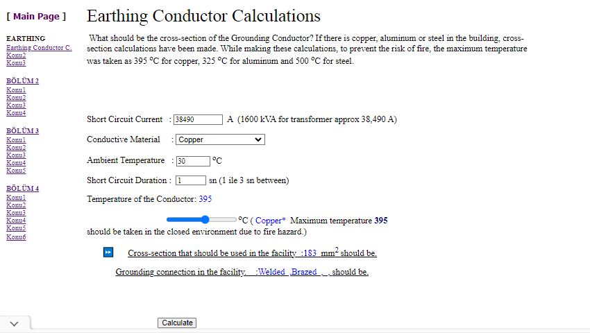
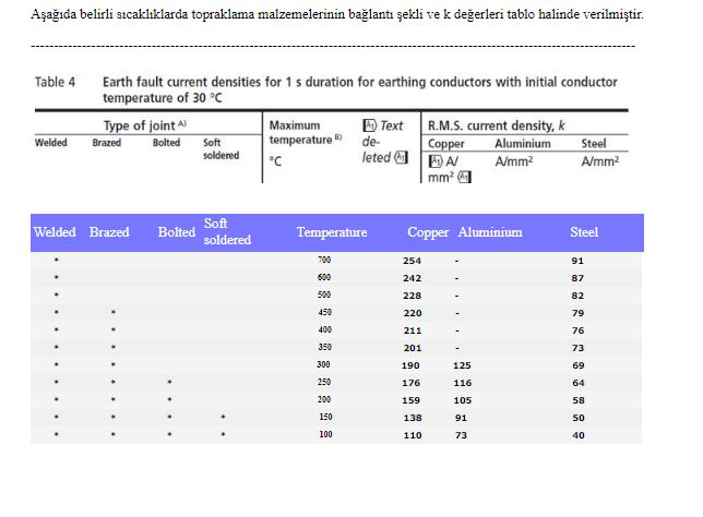
The approximate short circuit
current of the 1600 kVA transformer is taken as 38,000 A, and cross-section
calculations are made according to the selected grounding material.
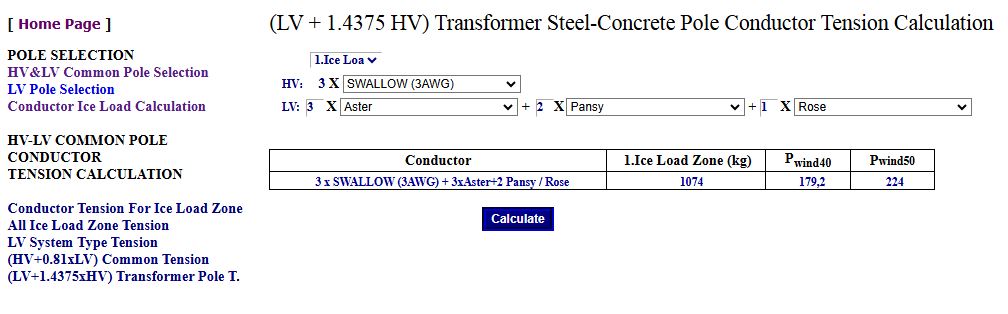
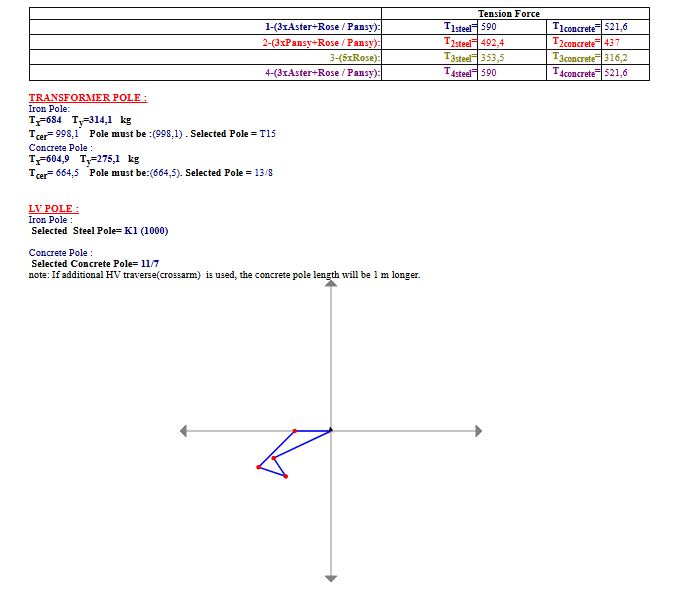
In Tension calculations, wind load is not taken
into account when the conductor wire is icy. It is obvious that wind will
blow even in icy conditions. Here, the force is calculated by assuming 100%
wind load on the conductor with Pbw. The total traction force on the
conductor was calculated with Pnw. This force should be taken into account to
prevent pole collapse, especially in places where winter conditions are
harsh.
In LV Networks, the traction forces of Alpek Cables are taken as HIGH, so HEAVY POLE are selected in the project calculations. This increases the facility costs. There are no Tension Calculations for Alpek Cables. Tension Calculations for these Conductors are Given. It is obvious that wind will blow even in icy conditions. Here, the force is calculated by assuming 100% wind load on the conductor with Pbw. The total Tension force on the conductor was calculated with Pnw. This force should be taken into account to prevent pole collapse, especially in places where winter conditions are harsh.
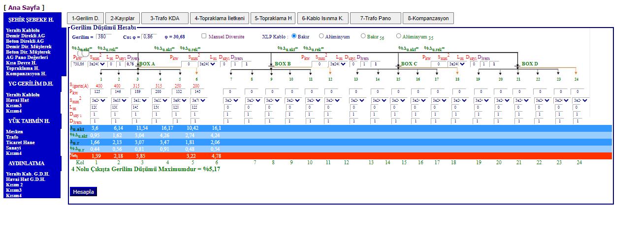
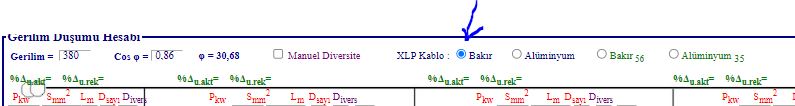
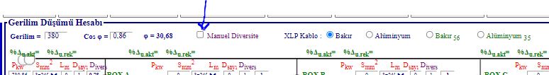
1-LV Copper or Aluminum XLPE cable can be selected in the program. (Aluminum
AG cable is not currently used.)
2-Calculations are made automatically based on cable impedance values. If desired, you can choose from the radio buttons; Calculations can be renewed according to the conductivity coefficients of 56 for copper and 35 for aluminum. 3- In BOX diversity calculation is done automatically. If desired, diversity can be adjusted by selecting Manual Diversity from the check box. 4-Residential subscribers were taken into account in the calculations and included in the calculations as Cos φ = 0.86. If desired, the calculations can be renewed by changing the Cos φ value. 5-The program calculates the active and reactive voltage drops separately according to Cos φ, and the total voltage drop is given in the red striped section. The program automatically finds the arm with the highest voltage drop.
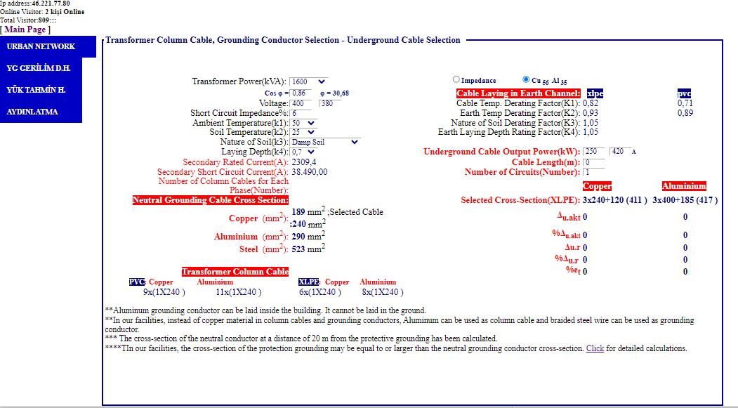
Transformer Column Cable
Calculation, Underground Cable Selection Calculations Made for Aluminum and
Copper Cables. 2-Neutral grounding in transformers was applied as 20 mt 1x50, but it has been changed to 1xColumn Cable Section. Here, the neutral grounding conductor cross-section calculation, which should be according to the Transformer Power, is made for Copper, Aluminum and Steel. Aluminum can be used as a grounding bar inside the building, but Copper or Steel Braided can be used in the ground. In field acceptance, it is seen that the transformer building protection grounding was done incorrectly with only 1x95 galvanized steel braided wire. This should be noted. 4- Considering the possibility of transformer power increase in the future, it would be appropriate to make grounding cross-section calculations according to the maximum power that can be placed in the transformer building. For pole type transformers, it would be appropriate to install them according to 400 kVA. 5-In our facilities, the cross-section of the protection grounding must be equal to or larger than the neutral conductor cross-section. 6-Cable heating controls are made according to Channel Depth, Soil Type, Soil Temperature, and the cable cross-sections required according to the entered power value are made for XLPE Copper and Aluminum. According to the cable impedance values or by selecting from the radio button; Calculations can be renewed according to the conductivity coefficients of 56 for copper and 35 for aluminum. a) It would be appropriate to choose the wet type in coastal areas. It would be appropriate to choose the extremely wet type for the Black Sea Region. b) In underground cable cross-section calculations, the channel depth should be selected in accordance with the project.
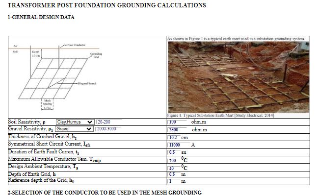
FOUNDATION MESH GROUNDING in Transformer Centers and Distribution Centers
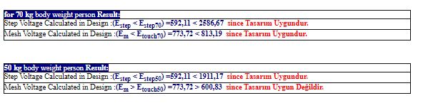
must be designed according to the allowable step voltage and contact voltage.
The calculations are made for a 70 kg personnel who will work here. (In
addition, calculations are given for a 50 kg human body. The following
information must be entered for the calculations.
1-The soil resistance of the place where the foundation grounding will be done should be measured and this value should be entered into the system. 2-The type of conductor to be used in foundation grounding must be selected from the menu. 3-When the short circuit current magnitude that may occur in the system is entered, the cross-section of the conductor to be used in foundation (network) grounding is calculated. 4-The size of the area to be grounded must be entered in terms of width and length. 5- By entering (changing) the distance between parallel conductors to be used in Foundation Grounding (eye, cell dimensions), the program checks whether the calculated step and contact voltages are appropriate. Foundation (network) grounding Project should be drawn according to this appropriate value. The program is available in the Foundation (network) grounding section of the Technical Calculations Menu.
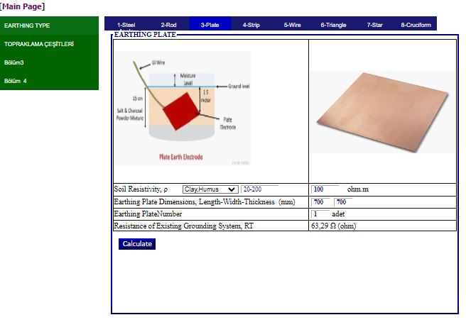
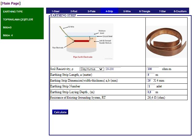
Calculations have been made for the grounding materials used in electrical
installations such as grounding stakes (angle brackets), rods, strips and
plates.
1-The soil resistance of the place to be grounded must be measured and the found value must be used in the formula. The 4 rods of the Soil Megger are driven into the soil at 2 or 4 m intervals and the soil resistance is measured by measuring at the soil resistance measurement level of the Soil Megger. 2-Calculations are given according to the grounding materials and shapes used.
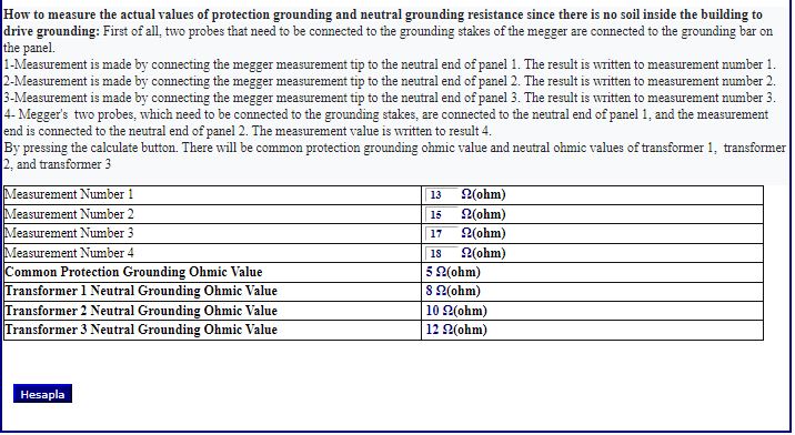
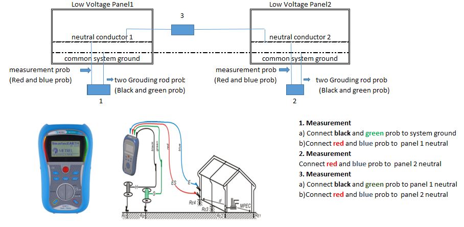
Since grounding piles cannot be
driven inside the building, measurements made with Megger only measure
whether there is soil contact. The real value of protection and operational
grounding cannot be measured. For this reason, it is not possible to
understand whether the grounding resistance values are within the values
required by the standards, and there are difficulties in the acceptance
process. With the method used here, the REAL values of protection and
operating earth resistances can be found. Field tests were conducted and it
was shown that the method used was correct. For example, if there are three
transformers under the building, the measurement is made as follows.
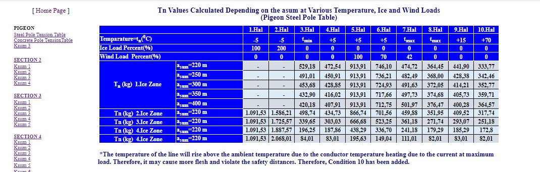
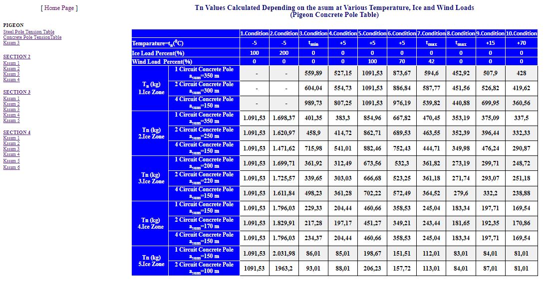
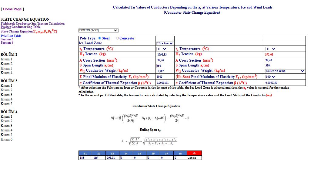
It is extremely important to make correct Tn tension calculations according to the asum of ice load zones for each conductor used in Power Distribution Line calculations. In project approvals, Tn tension calculations are made for 9 situations related to the asum for maximum tension, deflection and oscillation calculations. ERRORS have been detected in the tension forces released depending on the asum according to the ice load areas of the line. For example, in the 4-circuit project with pigeon concrete poles, the Tn tension force at asum=150m for minimum temperature was erroneously published as 198.22. However, this value should be 498.23 (Approximately 2.51 times). These published tables of the conductors used in distribution line must be recalculated and published in order to carry out the project control and approval procedures properly
In the Distribution line calculations, in the 8.condition control, the tension calculation is given at the maximum ambient temperature of the ice load region. However, at maximum load, the line temperature will heat up due to the current and the temperature of the line will rise above the ambient temperature. Therefore, the conductor may flesh further due to overheating and violate the safety distances. Especially when Renewable energy (Solar, wind) power plants operate at full load, the maximum temperature of the conductor can reach 70-80 0C. Safety distances should be checked with the flesh for 70 0C in the prepared flesh templates. It is generally observed that the wires have excessive runout at the beginning of the line in swallow distribution line operating at full capacity. It is seen that the flesh temple values in the ENH Project calculations are calculated high. Even if the pole types are selected correctly in the distribution line project calculations, the project loses its validity if the wire drawing calculations made depending on the temperature are made incorrectly. Therefore, in -5, 100% icy conditions, the wires are stretched much more, and therefore the poles can collapse more easily because the poles are under more than normal load.
Pigeon Line Tension tables have been calculated and republished. You can access the corrected tables by clicking High Voltage Distribution Line Menu Line Tension Table Tab.
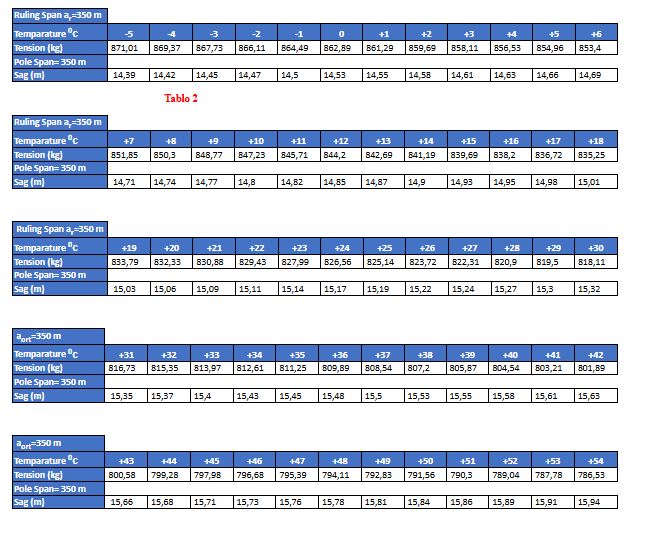
1-tension and Sag Calculations
must be made by taking into account the ACTUAL WIND SPEED and TEMPERATURE
during conductor installations in the field. In the program; You can access the program by clicking on the Fieldwork Conductor Sag Tension Calculation Fieldwork Conductor Sag Tension Calculation in the HV Overhead Distribution Lines Menu.
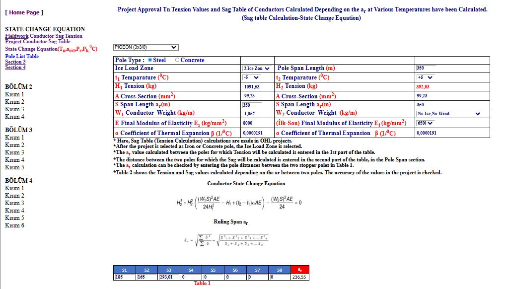
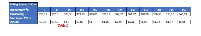
2-Checking the Sag TABLE Tables
Calculated in Project Approvals. You can access the program by clicking on the Fieldwork Conductor Sag Tension Calculation Project Conductor Sag Table in the HV Overhead Distribution Lines Menu.
3-Calculation of Conductor Tension
Tn(aorta,Pr,Pb,0C) According to Ice Load Regions. (Conductor State Change
Equation).
Mustafa Kemal Atatürk;[b] c. 1881[c] – 10 November 1938) was a Turkish field marshal, revolutionary statesman, author, and the founding father of the Republic of Turkey, serving as its first president from 1923 until his death in 1938. He undertook sweeping progressive reforms, which modernized Turkey into a secular, industrializing nation. Due to his military and political accomplishments, Atatürk is regarded as one of the most important political leaders of the 20th century.
We Commemorate The Founder Of Our Republic, The GREAT STATESMAN Gazi Mustafa Kemal ATATÜRK And His Comrades In Arms, Who Saved Us From Being Slaves And Devoted His Life To The Welfare And Happiness Of The Nation.
In the memories here, it will be seen how a great statesman who devoted his life to the welfare and happiness of the Turkish nation approached and solved the problems of his citizens, and will give an idea about his personality and nature. You can access page by clicking on the Atatürk's Memories in the Other Menu. Memories From ATATURK. and numerology of Atatürk Numerology From ATATURK.
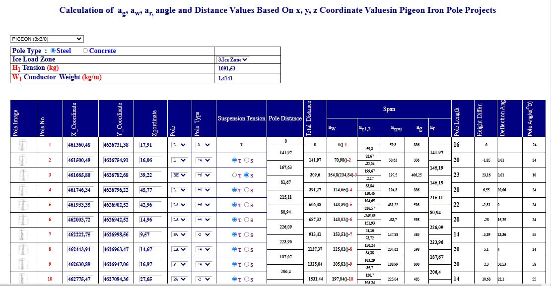
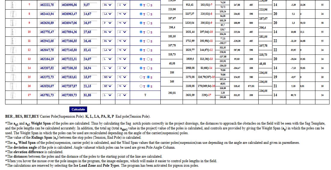
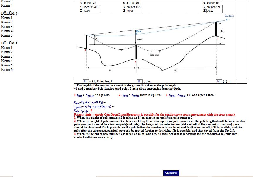
Just Entering The x,y,z Value:
*The
ag1 and ag2
Weight Span of the poles are
calculated. Thus by calculating the Sag notch points correctly in
the project drawings, the distances to approach the obstacles on the field
will be seen with the Sag Template, and the pole lengths can be calculated
accurately. In addition, the total ag (total agprj
value in the project) value of the poles is calculated, and controls are
provided by giving the Weight Span (ag)
in which the poles can be used. The Weight Span in which the poles can be
used are recalculated depending on the angle of the carrier(suspension)
poles. You can access the program by clicking on Calculationg, aw, ar, angle and distanceate in the HV Overhead Distribution Lines Menu.
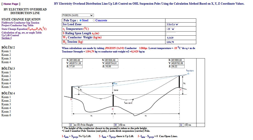
In Over Head Line projects,
fmin curve is used to check whether
the carrier(Suspension) poles are exposed to Up Lift. If the
fmin curve remains above the
suspension point of the conductor, it is directly exposed to Up Lift.
Sometimes the fmin curve may be very
close to this point. In this case, it should be checked
by calculation method whether the carrier (Suspension) pole under
control is exposed to Up Lift. You can access the program by clicking on Up Lift Control Tab in the HV Overhead Distribution Lines Menu.
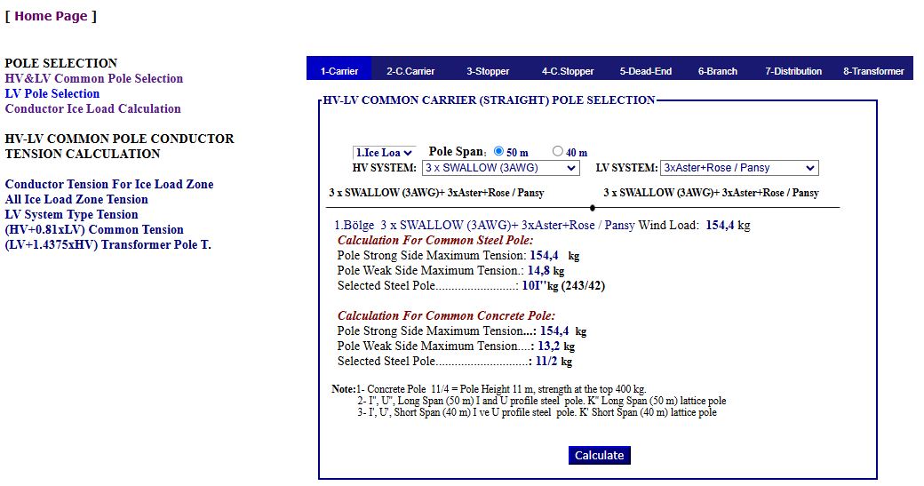
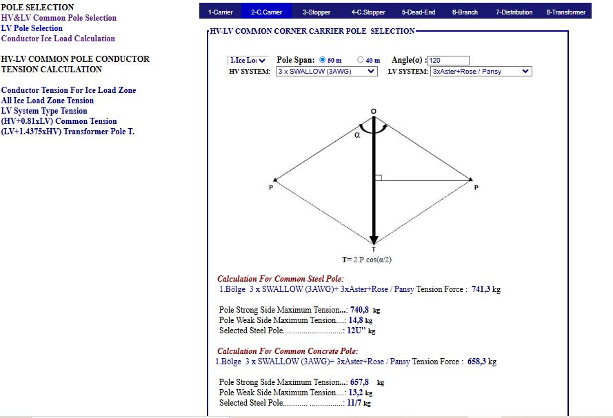
Calculations were made taking into account the HV&LV type systems conductors, critical situations and loads, and safety distances according to the typified iron and concrete poles used in 4 ice load regions in Turkey. If these calculations are not made correctly: If heavier poles are selected, facility costs will increase unnecessarily. If lighter poles are selected, defects and malfunctions may occur in the facility. In the program: 1- Tensions are calculated
according to the HV and LV conductor arrangements used in City and Village
networks and the loads on the pole are calculated.
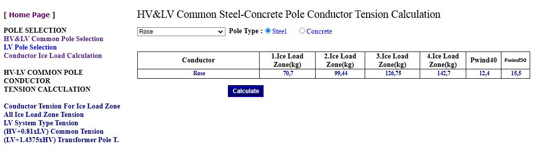
*Ice, wind loads and critical temperature values of the conductors according to the 4 ice load zones can be accessed from the LV Overhead Line Tension tab in the Rural Network Menu. *Tensions calculated for iron poles and concrete poles according to the conductor arrangements for the 4 ice load zones in Turkey will be published on a separate page.
You can access the program by clicking on HV&LV Common Pole Selection Tab in the Urban Network Menu.
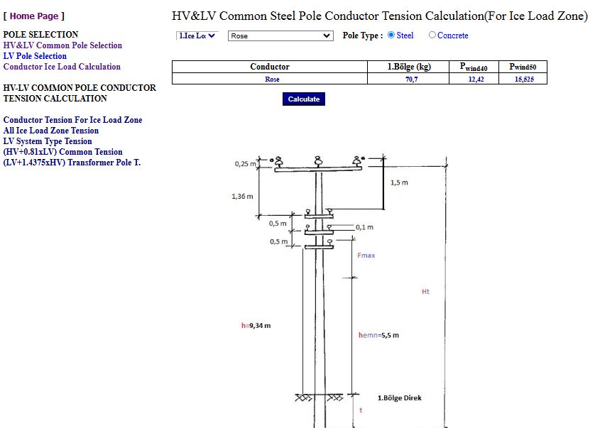
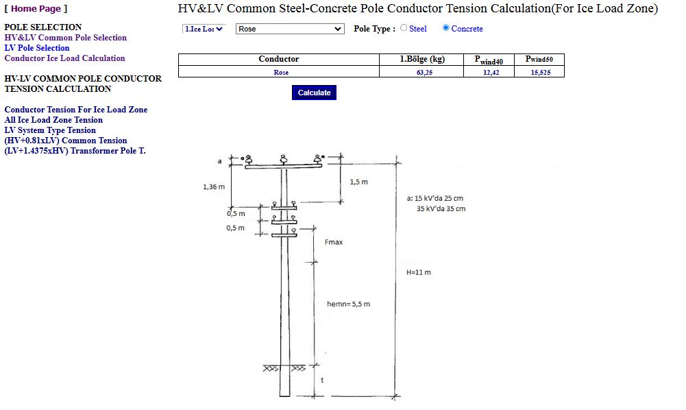
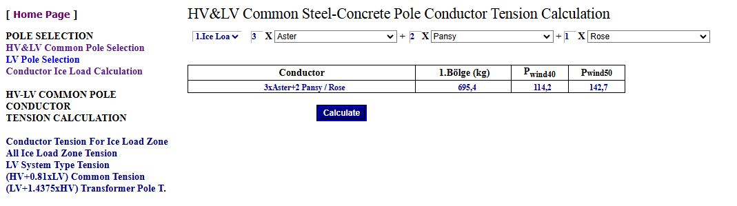
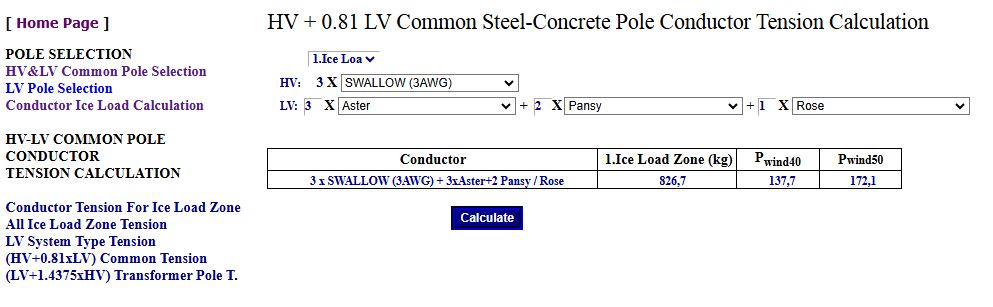
Tension calculations were made for the conductor System Type used in the typical common iron and concrete poles in 4 ice load regions in Turkey. In the program: 1-
Conductor Tension For Ice Load Zone : When this option is
clicked, HV, LV conductors are selected according to the ice load regions and
tension calculations and wind loads are calculated for common concrete and
iron poles. You can access the program by clicking on HV&LV Conductor System Type Tension Tab in the Urban Network Menu.
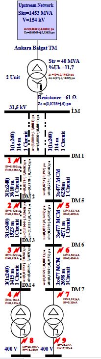
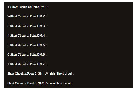
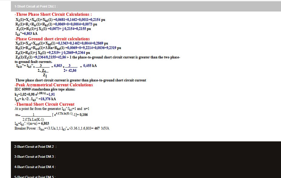
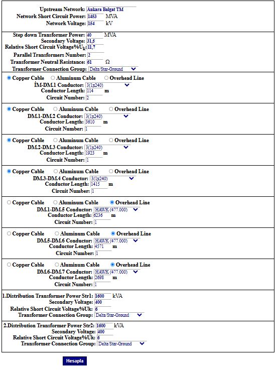
Short circuit calculations are made using the Per Unit method. Transformer, conductor parameters are entered and zero The positive sequence are calculated, three phase and phase ground short circuit calculations are made at 9 different points of the facility, all values are shown on a single line diagram. In the program; - Power,
%uk, Voltage, resistance values of transformers are entered. You can access the program by clicking on Short Circuit Current Calculations Tab in the technical calculations menu on the home page.
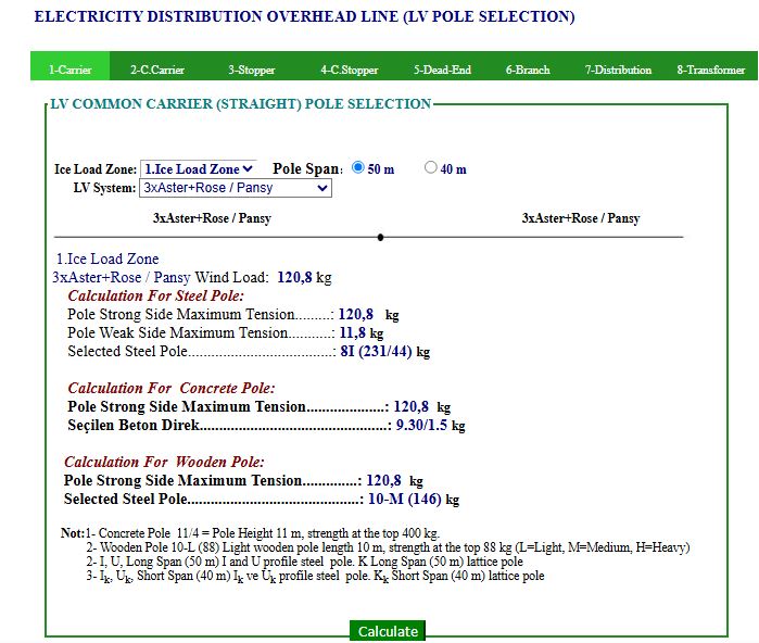
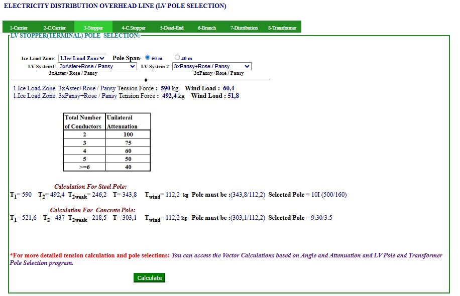
On common pole lines:
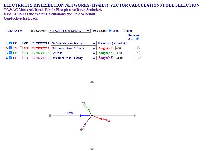
The program Select low voltage Pole type: wood, iron and concrete poles used in 4 ice load zone in Turkey, according to the conductor arrangement used. The program: 1- According to the LV conductor arrangements used in city and village networks, tension is calculated, loads coming to the pole are found and wood, iron and concrete poles that can be used are selected accordingly. 2- According to the functions of the poles; separate calculations are made and pole selections are made in case of carrier, corner carrier, stopper, corner stopper, end, branch, distribution and transformer poles. 3-LV vector calculations: All possibilities can be evaluated according to the resultant force or by applying attenuation to the desired conductor arrangement according to the different conductor arrangements and angle values of the poles, and pole selections can be made by determining the worst-case scenario accordingly. 4- In Turkey, the LV overhead Line type tension calculated for iron and concrete poles according to 4 ice load zone are published under the Rural Network Menu Conductor Tension For Ice Load Zone tab.
You can access the page by clicking on the LV Overhead Line Pole Selection tab in the Rural Network Menu on the home page.
* The Tension of LV and HV conductors has been recalculated by taking into account critical conditions and loads, safety distances. Pole selections are made according to these newly calculated values. If these calculations are not made correctly: If heavier poles are selected, facility costs will increase unnecessarily. If lighter poles are selected, malfunctions and failures may occur in the facility. The accuracy of these newly calculated values can be tested by checking the critical conditions and safety distances.
|
Mail: Hakan ALTIN